
01
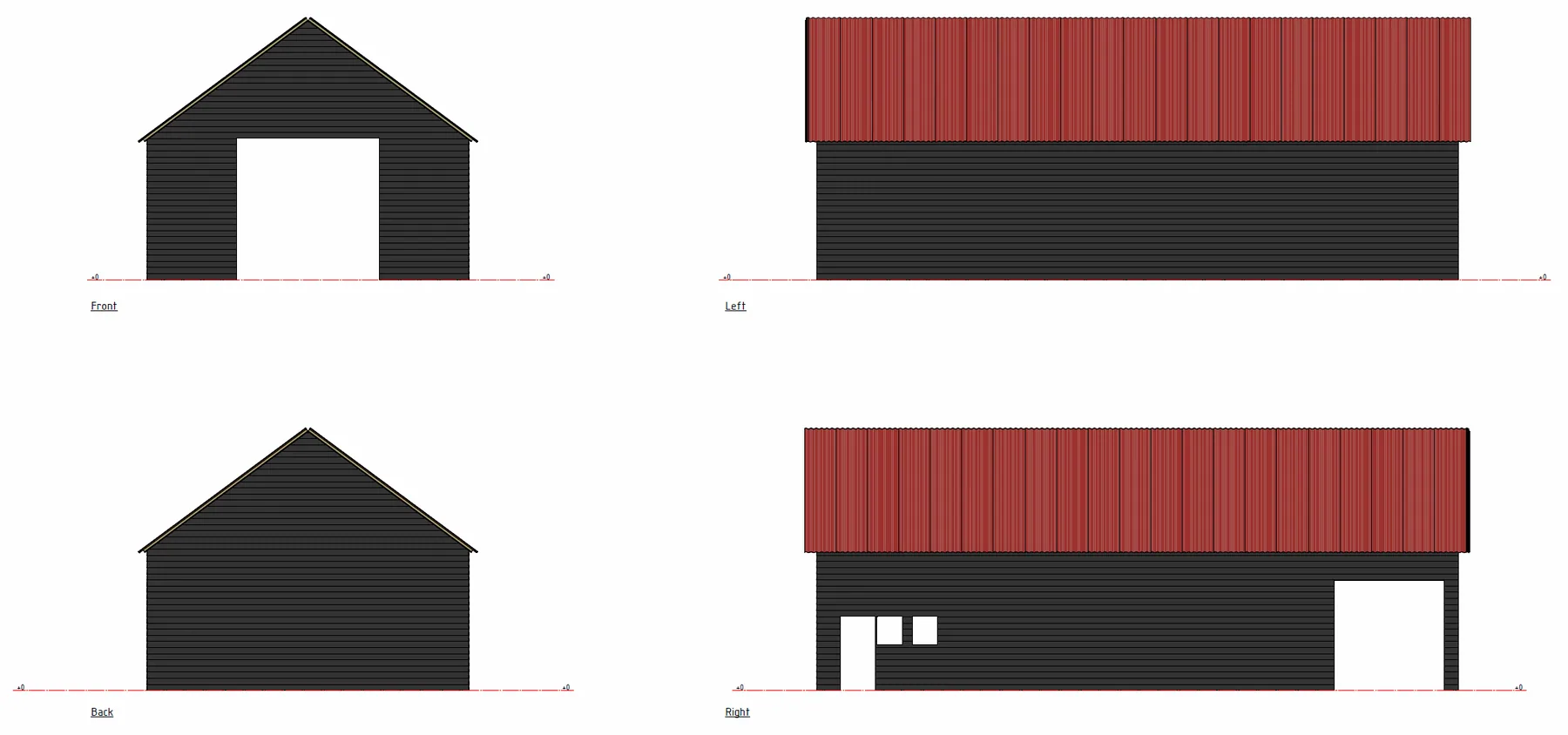
Shop drawings
Elevations showing the layout, dimensions and marking of sandwich panels and flashings.
BIM
We turn engineers' designs into complete shop drawings and production documentation: a 3D model of the building, elevations, details and material schedules — panels, flashings, trims and accessories.
For designers, main contractors and installation companies
Massing and structure in a single model that every drawing is generated from.
Drawings ready for issue to the factory and to site.
A complete set of views generated from the model — no inconsistencies between sheets.
Junctions, corners and penetrations at a scale the site team can work from.
Panel schedule with dimensions, thicknesses and position marks.
Trims, cover strips, flashings and accessories — with lengths and quantities.
The model, drawings, schedules and visualisations all come from a single data source, which keeps the documentation consistent at every stage of the project.
Elevations showing the layout, dimensions and marking of sandwich panels and flashings.
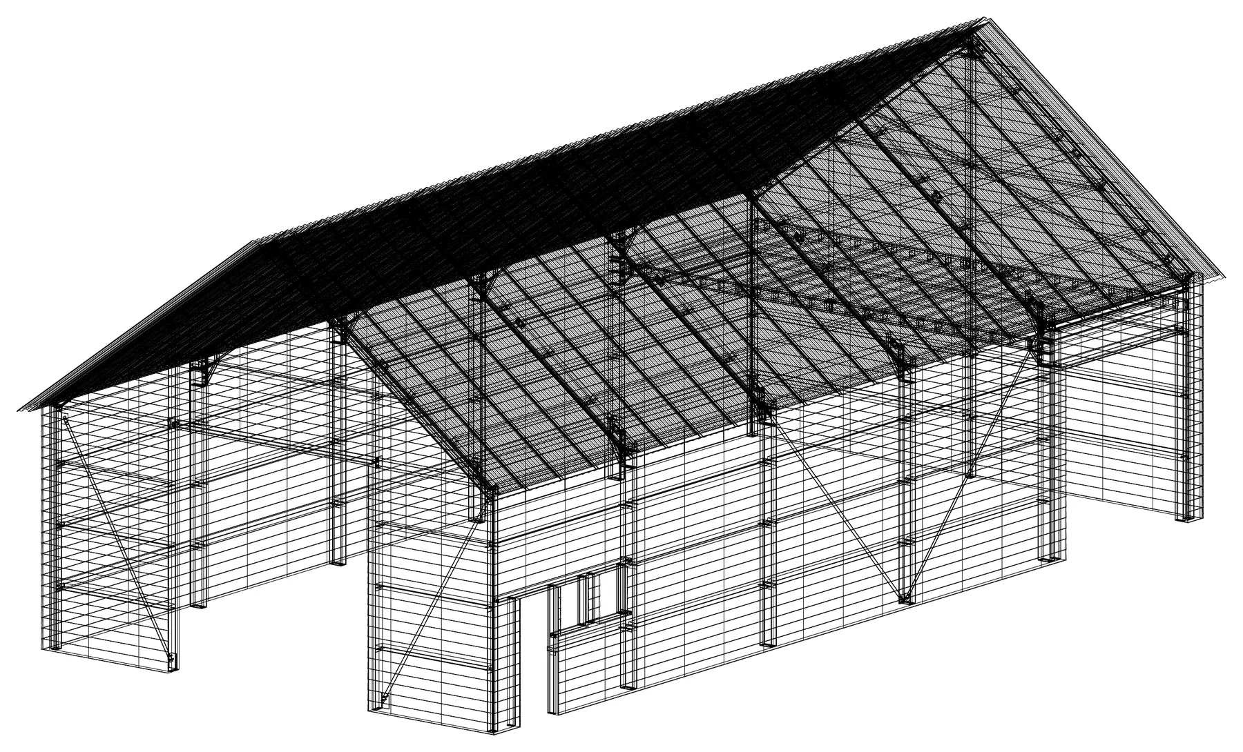
A model of the structure and cladding, built from approved engineering documentation.
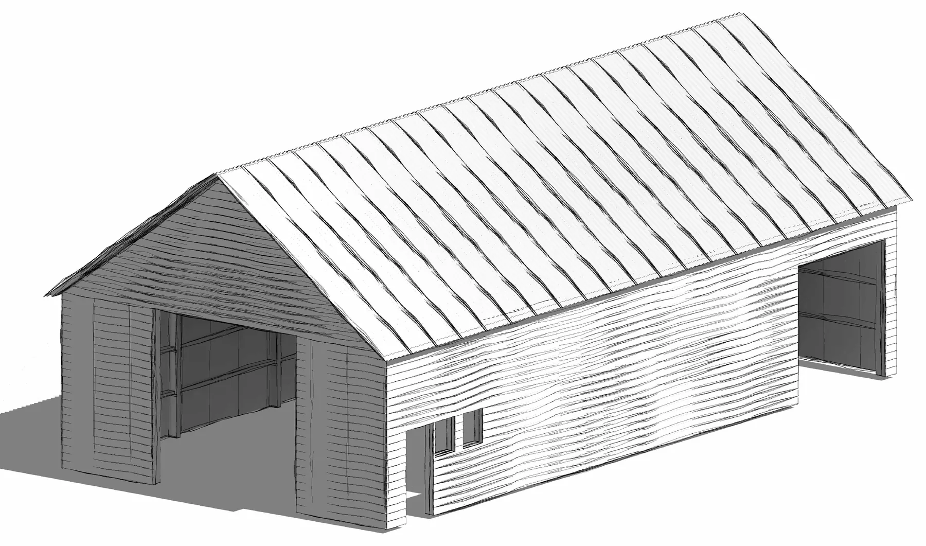
Wall and roof panel layout, geometry checks and data prepared for production and installation.
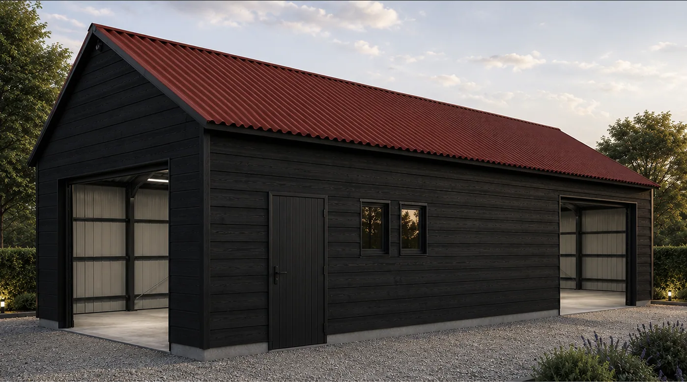
The building shown in its final materials and colours — for sign-off before work starts.
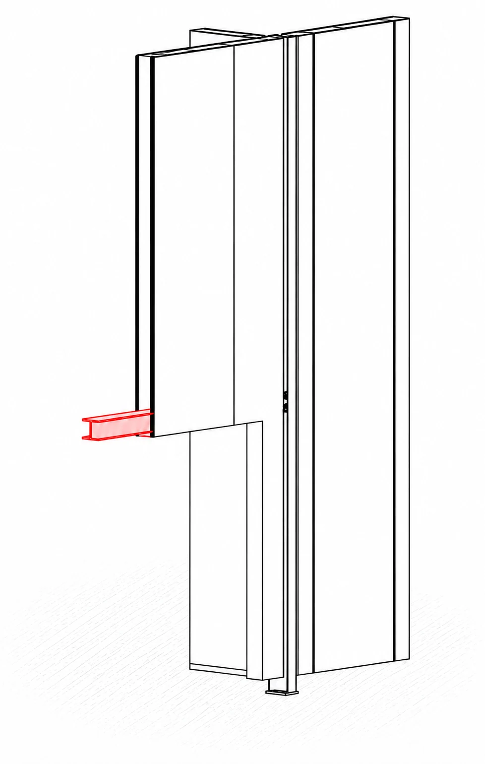
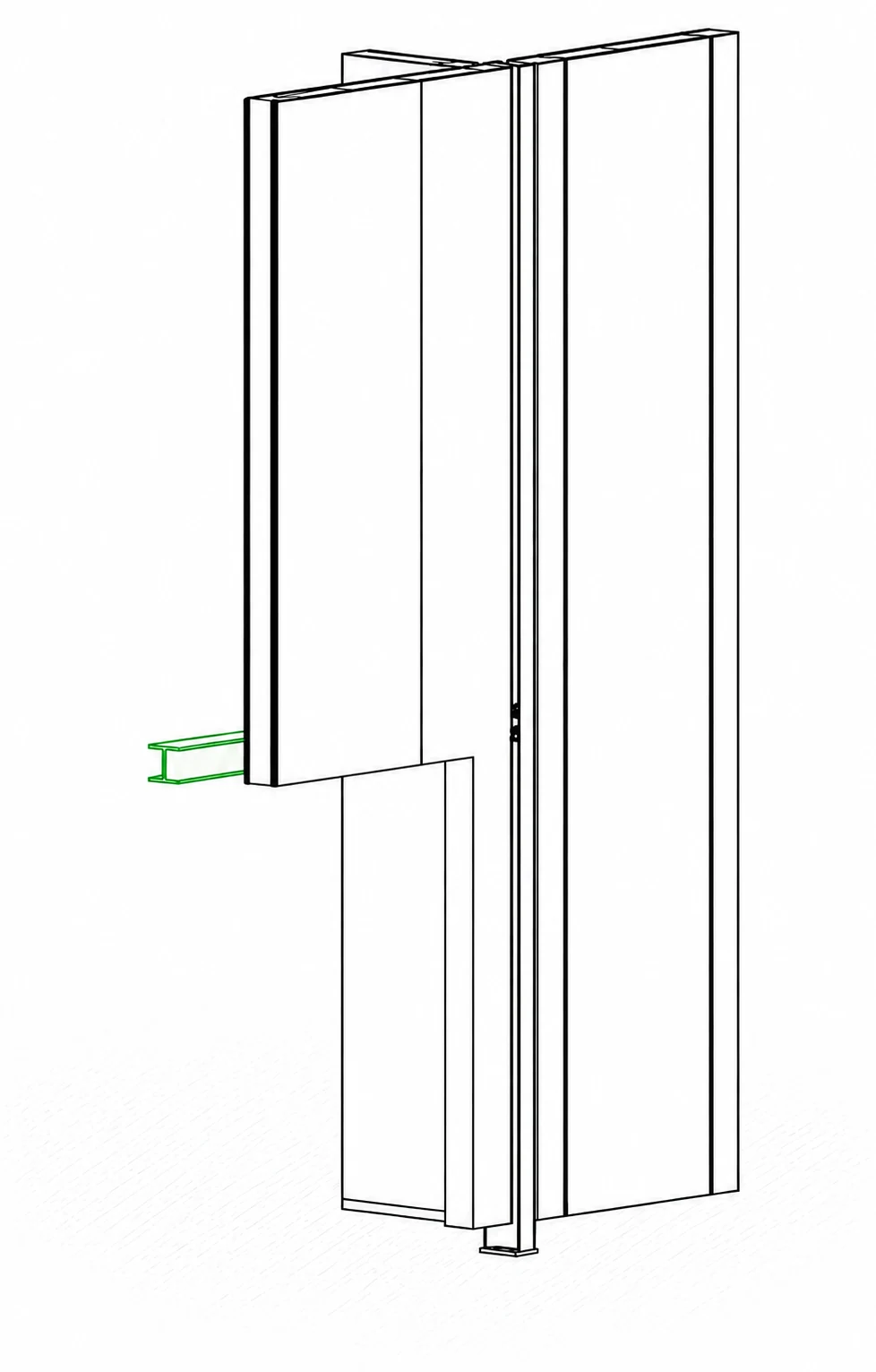
A 3D model lets us check connections, geometry and the position of components before installation starts. Clashes are resolved in the documentation, not on site.
While modelling, we found a clash between the steel structure and a wall with a door opening. We raised it with the design engineer responsible, and the beam was repositioned before production and installation started.
No rework on site. No delays. No last-minute fixes during installation.
Better to say this now than at the third meeting.
We receive the design, the assumptions and the technical solutions from the engineer.
We build the 3D model at an agreed level of detail.
We generate shop drawings, elevations and details.
We issue panel, flashing and accessory schedules.